ASUS Maximus Formula SE: X38 and DDR2 Unite!
by Rajinder Gill on November 9, 2007 7:00 AM EST- Posted in
- Motherboards
Board Layout and Features
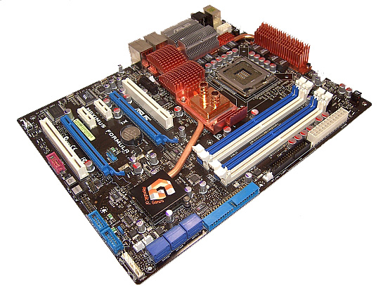
There are no surprises here; ASUS delivers the standard ROG color scheme consisting of blue and white slots, while sticking with the same overall layout we have seen in earlier ROG boards. There are eight on-board fan headers, which are controllable either through the BIOS or with the supplied PC Probe II software via the OS. The three OPT fan headers have probe connectors situated nearby and are compatible with probe related fan speed controls (the probes are sold separately). The whole board utilizes solid polymer capacitors, which are mandatory on the ROG series.
ASUS has also included a "Volt Minder" system that uses traffic light colored LEDs placed near the CPU, Northbridge, and Southbridge. These LEDs light up to signal the level of voltage applied; Green is safe or normal range, yellow for high voltage, and red is referred to as "crazy voltage levels" by ASUS - rightly so when you look at the available levels of voltage to these areas in the BIOS. Overall, the general layout, features, and slot placement is ideal for an overclocking oriented motherboard.
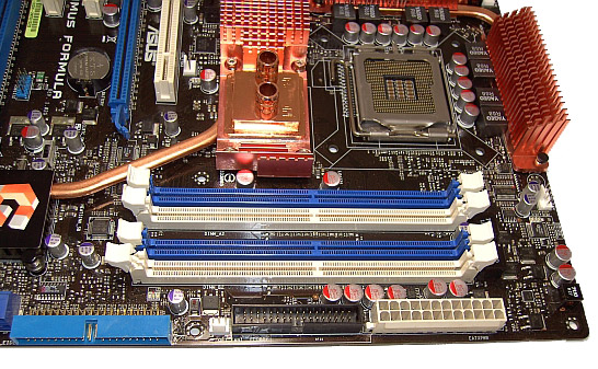
The DIMM sockets are located a little lower on this board; ASUS has moved the slots closer to the Northbridge, shortening the PCB trace lengths (in theory reducing inductance and signal crosstalk). We had no issues inserting or removing our 4x1GB memory modules from the DIMM slots, even with a long graphics card inserted into the primary PEG slot. Memory voltage is supplied by a two-phase power circuit, which has become another ROG motherboard trademark. With 4GB of memory becoming increasingly popular, the lower impedance should help sustain stable high MHz memory clocking. The 24-pin ATX header is located conveniently at the edge of the board, alongside the floppy drive and a fan/probe connector, all accessible without hindrance from other components.
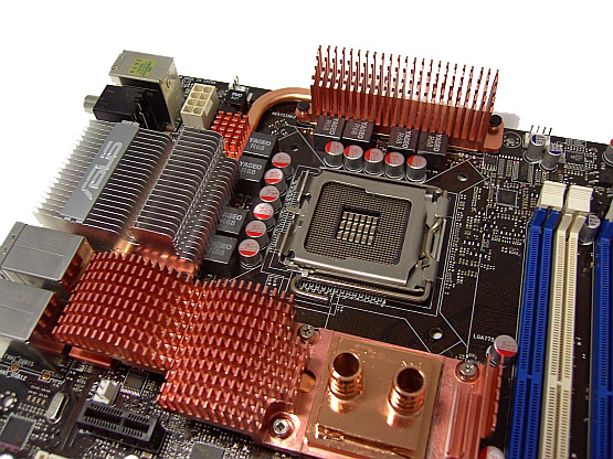
CPU power is supplied by an eight-phase analog PWM circuit, using high quality Yageo inductors. The 8-pin 12V connector is located at the top left corner of the board, just behind the PS/2 connectors. This board is clearly aimed at users who are likely to water-cool both the CPU and Northbridge. Mounting air coolers that use thumbscrews for attachment is made a little awkward by the close proximity of the large Northbridge heatsink around the lower left corner of the CPU socket. A fan header is placed at the top edge of the board. We also have an SPDIF output header, and the top left of the board is home for the supplied LCD post display connector. Thankfully, ASUS listened to users and the LCD post display comes with its own cable allowing for user-selected placement.
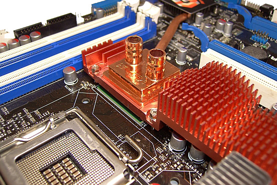
Moving on, we find the elaborate ROG heatsink designs ASUS employs to cool the Northbridge, Southbridge, and PWM areas. For the Maximus Formula SE, ASUS has employed a hybrid design consisting of a water block that is spot epoxy glued to a large heatsink that connects the Southbridge and Northbridge together with a heatpipe. The heatpipe continues further, covering part of the separate PWM heatsink, with an Aluminum fin section. A small fan is supplied that clips onto the Aluminum section of the heatsink, helping to cool the Northbridge and we suggest using it.
ASUS supplies both 3/8" and 1/2" tubing adaptors together with spring clamps to hold tubing in place. Unfortunately, our high flow pumps (Petra Top DDC Ultras) were too much for the 1/2" spring clamps. Using the supplied 1/2" clamps, our tubing actually came loose and shot off the barbs. Bottom line: screw type hose clips are a safer bet for high-pressure water cooling pumps. Initial testing with the stock solution using our upper-end water-cooling solution showed little temperature gains over air-cooling using 2x120mm fans over the area. During testing our water block actually came loose, and we were a little surprised to find that there was little contact between the heatsink and NB water block. No thermal paste was used in the stock design to ensure contact between the spots of epoxy glue that had been used to bond the two surfaces together.
Because there was very little contact between the Northbridge water block and the heatsink, it's no wonder there were no initial gains from using water-cooling. We re-attached the block using a combination of thermal paste (in the center of the block) and epoxy (around the perimeter). We also checked the contact between the chipset IHS (Integrated Heat Spreader) and the Northbridge heatsink assembly. The footprint left by the pad showed around a 60% contact surface, with the center of the NB IHS making very little contact with the heatsink. We scraped away the flaky thermal pad and used thermal paste in its place. The increased surface contact of the two modifications lead to a ~9C drop in load temperatures and certainly helped in overall board stability when overclocking. Needless to say, this is not the sort of thing users should be required to do on an "extreme" motherboard. Hopefully ASUS can improve their process and quality control on this aspect of the Maximus. In fact, ASUS has shipped us a new board that should arrive shortly so we can compare early production process to the current one.
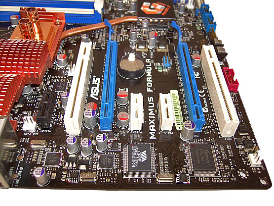
There are two PCI-E 2.0 x16 slots, both offering full x16 bandwidth for dual graphics cards. The remaining slots are three PCI-E x1 (the black slot is reserved for the supplied SupremeFX II ADI based 8-CH Audio card), and two PCI 2.3 slots, placed in between the PCI Express slots. The wide PCI Express slot spacing should help airflow, especially with high heat producing cards such as the AMD HD 2900 series. Underneath the lower PCI slot, we have a fan and thermal probe header. Further to the right we have an on-board 1394a port connector and power and reset switches. One of the Internal USB connectors is placed over the lower PCI Express x16 slot; the other two internal USB connectors are situated to the right of the power and reset switches.
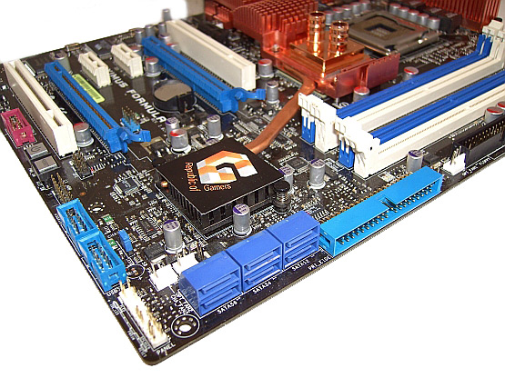
The Intel ICH9R Southbridge has the standard six on-board SATA sockets, placed at a 90 degree angle towards the right edge of the board. If the motherboard is to be mounted in small PC cases, it is wise to plug the SATA cables in before securing the motherboard into the case. Underneath the SATA ports we have the system panel connector, featuring ASUS' easy mount Q-Connector system. Two more fan headers and a thermal probe header sit behind the SATA ports.
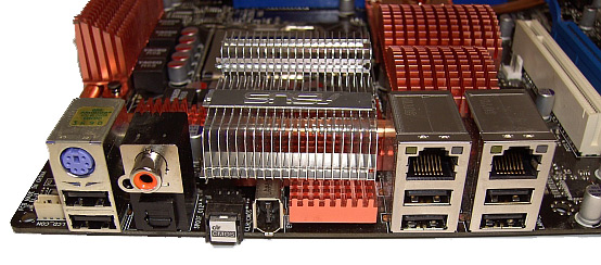
Rear IO ports feature a PS/2 keyboard port with 2 USB slots directly underneath; users with a PS/2 mouse will need a PS/2 to USB adaptor. A Coaxial S/PDIF output is also present, together with a TOSLINK output. To the right we have the Clear CMOS button, making it easy to clear the CMOS after the board is installed in a case. There is a rear FireWire port, dual Gigabit LAN (featuring teaming support), and four additional USB ports. ASUS also bundles 3DMark06 (Advanced Edition), STALKER, and Kaspersky anti-virus software with the board.

There are no surprises here; ASUS delivers the standard ROG color scheme consisting of blue and white slots, while sticking with the same overall layout we have seen in earlier ROG boards. There are eight on-board fan headers, which are controllable either through the BIOS or with the supplied PC Probe II software via the OS. The three OPT fan headers have probe connectors situated nearby and are compatible with probe related fan speed controls (the probes are sold separately). The whole board utilizes solid polymer capacitors, which are mandatory on the ROG series.
ASUS has also included a "Volt Minder" system that uses traffic light colored LEDs placed near the CPU, Northbridge, and Southbridge. These LEDs light up to signal the level of voltage applied; Green is safe or normal range, yellow for high voltage, and red is referred to as "crazy voltage levels" by ASUS - rightly so when you look at the available levels of voltage to these areas in the BIOS. Overall, the general layout, features, and slot placement is ideal for an overclocking oriented motherboard.

The DIMM sockets are located a little lower on this board; ASUS has moved the slots closer to the Northbridge, shortening the PCB trace lengths (in theory reducing inductance and signal crosstalk). We had no issues inserting or removing our 4x1GB memory modules from the DIMM slots, even with a long graphics card inserted into the primary PEG slot. Memory voltage is supplied by a two-phase power circuit, which has become another ROG motherboard trademark. With 4GB of memory becoming increasingly popular, the lower impedance should help sustain stable high MHz memory clocking. The 24-pin ATX header is located conveniently at the edge of the board, alongside the floppy drive and a fan/probe connector, all accessible without hindrance from other components.

CPU power is supplied by an eight-phase analog PWM circuit, using high quality Yageo inductors. The 8-pin 12V connector is located at the top left corner of the board, just behind the PS/2 connectors. This board is clearly aimed at users who are likely to water-cool both the CPU and Northbridge. Mounting air coolers that use thumbscrews for attachment is made a little awkward by the close proximity of the large Northbridge heatsink around the lower left corner of the CPU socket. A fan header is placed at the top edge of the board. We also have an SPDIF output header, and the top left of the board is home for the supplied LCD post display connector. Thankfully, ASUS listened to users and the LCD post display comes with its own cable allowing for user-selected placement.

Moving on, we find the elaborate ROG heatsink designs ASUS employs to cool the Northbridge, Southbridge, and PWM areas. For the Maximus Formula SE, ASUS has employed a hybrid design consisting of a water block that is spot epoxy glued to a large heatsink that connects the Southbridge and Northbridge together with a heatpipe. The heatpipe continues further, covering part of the separate PWM heatsink, with an Aluminum fin section. A small fan is supplied that clips onto the Aluminum section of the heatsink, helping to cool the Northbridge and we suggest using it.
ASUS supplies both 3/8" and 1/2" tubing adaptors together with spring clamps to hold tubing in place. Unfortunately, our high flow pumps (Petra Top DDC Ultras) were too much for the 1/2" spring clamps. Using the supplied 1/2" clamps, our tubing actually came loose and shot off the barbs. Bottom line: screw type hose clips are a safer bet for high-pressure water cooling pumps. Initial testing with the stock solution using our upper-end water-cooling solution showed little temperature gains over air-cooling using 2x120mm fans over the area. During testing our water block actually came loose, and we were a little surprised to find that there was little contact between the heatsink and NB water block. No thermal paste was used in the stock design to ensure contact between the spots of epoxy glue that had been used to bond the two surfaces together.
Because there was very little contact between the Northbridge water block and the heatsink, it's no wonder there were no initial gains from using water-cooling. We re-attached the block using a combination of thermal paste (in the center of the block) and epoxy (around the perimeter). We also checked the contact between the chipset IHS (Integrated Heat Spreader) and the Northbridge heatsink assembly. The footprint left by the pad showed around a 60% contact surface, with the center of the NB IHS making very little contact with the heatsink. We scraped away the flaky thermal pad and used thermal paste in its place. The increased surface contact of the two modifications lead to a ~9C drop in load temperatures and certainly helped in overall board stability when overclocking. Needless to say, this is not the sort of thing users should be required to do on an "extreme" motherboard. Hopefully ASUS can improve their process and quality control on this aspect of the Maximus. In fact, ASUS has shipped us a new board that should arrive shortly so we can compare early production process to the current one.

There are two PCI-E 2.0 x16 slots, both offering full x16 bandwidth for dual graphics cards. The remaining slots are three PCI-E x1 (the black slot is reserved for the supplied SupremeFX II ADI based 8-CH Audio card), and two PCI 2.3 slots, placed in between the PCI Express slots. The wide PCI Express slot spacing should help airflow, especially with high heat producing cards such as the AMD HD 2900 series. Underneath the lower PCI slot, we have a fan and thermal probe header. Further to the right we have an on-board 1394a port connector and power and reset switches. One of the Internal USB connectors is placed over the lower PCI Express x16 slot; the other two internal USB connectors are situated to the right of the power and reset switches.

The Intel ICH9R Southbridge has the standard six on-board SATA sockets, placed at a 90 degree angle towards the right edge of the board. If the motherboard is to be mounted in small PC cases, it is wise to plug the SATA cables in before securing the motherboard into the case. Underneath the SATA ports we have the system panel connector, featuring ASUS' easy mount Q-Connector system. Two more fan headers and a thermal probe header sit behind the SATA ports.

Rear IO ports feature a PS/2 keyboard port with 2 USB slots directly underneath; users with a PS/2 mouse will need a PS/2 to USB adaptor. A Coaxial S/PDIF output is also present, together with a TOSLINK output. To the right we have the Clear CMOS button, making it easy to clear the CMOS after the board is installed in a case. There is a rear FireWire port, dual Gigabit LAN (featuring teaming support), and four additional USB ports. ASUS also bundles 3DMark06 (Advanced Edition), STALKER, and Kaspersky anti-virus software with the board.


24 Comments
View All Comments
mbf - Friday, November 9, 2007 - link
...handle DDR2 ECC memory? I for one would like to know. ASUS seems to be of two (or possibly more) minds on the matter stating conflicting information all around the product pages for their respective X38 board offerings. Then again, the P5W DH Deluxe still seems like a smart choice, considering the very small performance delta between the i975x and later chipsets. Also, ASUS claims Penryn support for several of their "mature" offerings, including the P5W DH Deluxe.AnnihilatorX - Friday, November 9, 2007 - link
Personally I would recommend everyone including enthusiasts to not to buy over-priced performance RAMs.And of course looking at price at the moment to choose DDR2 over DDR3
A low latency low frequency RAM are potentially *much* cheaper than a high frequency one. The performance discrepancy is at most 5% which relates to perhaps 2-3FPS in a game. This has probably the lowest cost-to-performance ratio of a system component.
steve4717 - Sunday, May 16, 2010 - link
when will the new bios be ready, and i exspect it, this time to make it possible so it can see, ddr2 1066 at long last.nleksan - Wednesday, November 28, 2012 - link
I have been looking for a motherboard for a recently acquired (given to me free of charge) set of somewhat older but almost entirely unused (i.e. no more than 100hrs use on anything, most have around 20-40hrs; came from 9 different full-or-partial PC's) hardware including:- Core2Duo E8600 (under 20hrs use, known to run stable at 4.5Ghz on air, 4.9Ghz on water)
- 4x2GB G.Skill DDR2-1066/1150 4-4-4-9
- 4x1GB OCZ DDR2-1066 4-4-4-12
- 3x 250GB Samsung Spinpoint SATA3Gbps HDD's
- 2x 150GB WD VR SATA3Gbps 10krpm HDD's
- 1x WD WD800BB 80GB SATA3Gbps HDD
- 4x WD2500JB 250GB SATA HDD's
- 3x WD Caviar Blue 320GB (AAKS) SATA3Gbps HDD's (repurposed for new X79 build)
- 2x Seagate 7200.7 160GB E-IDE HDD's
- 3x Hitachi Deskstar 320GB SATA3Gbps HDD's
- Enermax 690W High-Efficiency PSU
- Antec SOHO Server Case with 8x3.5" bays/5x5.25" bays (fits a Xigmatek 4x3.5-in-3x5.25 with 120x25mm fan converter nicely, for a total of 12xHDD's) and ripe for some heavy modifications
OR
- Thermaltake XASER V Limited Edition with 5x3.5" bays + 6x5.25" bays
OR
- Buy a new sub-$100 case for this (Rosewill ThorV2 would be nice for price, Antec 1100/1200/P283
- DD Maze6 CPU Block
- 2x DD Maze6 GPU Blocks
- 3x Swiftech MCW82 GPU Blocks
- Laing DDC3.25 + 2x Laing D5 Vario Pumps
- Swiftech MCRES-Rev2
- HWL Black Ice GTX 360 rad
- HWL Black Ice GTS 280 rad
- 4x Misc 120-240 Rads
- 11x Delta Fans (7x 120x38mm 2200-4500rpm up to 133cfm 14.25mmH2O, 4x 120x25 2400-4800rpm up to 155cfm 15.2mmH2O)
- 5x NIDEC Fans (120x38mm 0.98amps 11.5-13.2V, up to 4250rpm 151cfm 22.32mmH2O)
- >50x Misc 80x15/25/38mm, 92x25/38mm, 120x12/25/38mm, 140x25mm Fans
I have been looking for two things: a Motherboard and a GPU (or pair of GPU's), and while this will be a Home Server/Media Server, it will also function as a F@H box. I am thinking that 2x 9800GTX+'s or 2x GTX260 216core's in SLI would suffice, but perhaps not? I don't know much about the C2D/C2Q era MB's/GPU's....
I have been looking at the following boards:
- Asus P5Q Premium (huge amount of connections, would allow 4x GPU's for F@H or 3xGPU + 1x RAID Card)
- Asus Maximus Extreme
- Asus Rampage Extreme
For GPU's, I've been really considering the following, from lowest cost to highest:
- 2-3x 8800GTS 512MB (G92)
- 3x 8800GTX's
- 2-3x 9800GT's
- 2-3x 9800GTX+'s
- 2x 9800GTX2's
- 2-3x GTX260(216core)-to-GTX295's
- 2-3x GTX460's-to-GTX480's
Anyone remember enough about this older hardware to help me out?