ASUS Striker II Extreme: Mucho Bang, Mucho Bucks
by Kris Boughton on April 11, 2008 7:00 AM EST- Posted in
- Motherboards
ASUS Striker II Extreme Board Layout and Features
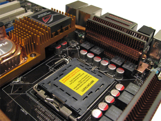
ASUS' third-generation advanced power delivery system is back and as good as ever. ASUS uses the finest ultra-low ESR, polymer capacitors from Fairchild and solid, low-DCR Yageo inductors. Simply noting the inductor count will tell you this board uses an 8-phase PWM, with one small twist though: the PWM buck controller really only supports true 4-phase operation but with an output multiplexer used to double the phase count. This means a sudden power demand placed on the system will only draw current from four of the phases while the other four sit idle, unattached from the load. From this perspective the native 6-phase design used on NVIDIA's reference boards, available from EVGA or XFX, might actually be the better solution.
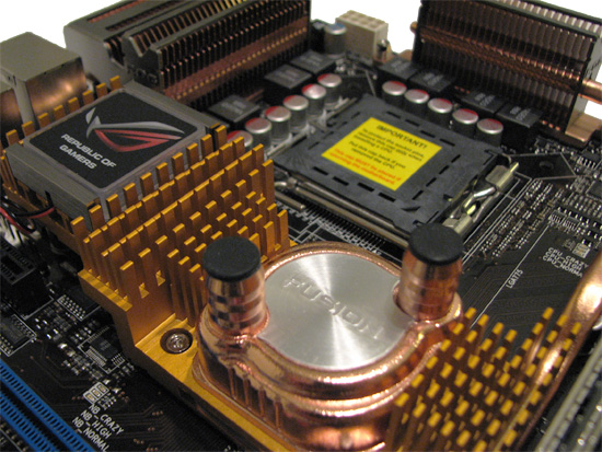
The portion of the heatsink covering the 790i SPP is extruded aluminum with a coating applied to give the illusion of copper. The integrated "Fusion" water-cooling bowl is covered with a thick copper finish inside and out ensuring there will be no issues with galvanic corrosion due to dissimilar metals. The barbs are only 3/8" inner diameter (ID) but a couple of plastic 3/8"-to-1/2" ID straight-through adapters and two 3/8" ID segments of tubing about one-half inch in length are included for those with 1/2" ID water-cooling loops. We found that removing, cleaning, and replacing the factory thermal interface material (TIM) with a small blob of OCZ Freeze was sufficient when it came to cooling the 790i SPP. The included back plates provided all the mounting pressure needed to securely fasten the stock heatsink back in place once we were done with the TIM swap-out.
The backlight for the small Republic of Gamer (R.O.G.) logo attached to the top-half of the heatsink can be turned on or off in the BIOS. Call us crazy but we think building up the fins here, providing more surface area for better heat dissipation seems like a more appropriate use of this precious space. Even a small fan would have been a better choice as far as we are concerned - aesthetics only go so far; every board should be as functional as possible.
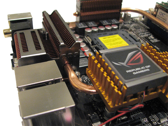
The coolers located above each bank of MOSFETs are made of high-quality copper, with an extra segment extending into the area immediately adjacent to the I/O panel. Everything is thermally joined to the SPP heatsink using a closed-loop copper heatpipe and a bit of brazing material. We were pleased to see that ASUS decided to start including back plates for the MOSFET coolers as well. These help to evenly distribute the pressures developed during mounting along the length of the cooler, making certain it sits flush atop the components below.
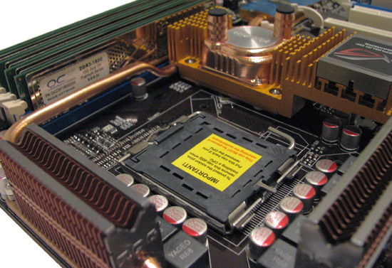
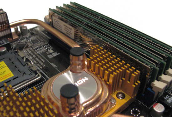
As with most good DDR3-based designs, the DIMMs are moved slightly down the board bringing them as close to the SPP as physically possible. This can sometimes make things quite cramped when trying to install a longer card in the top PCIe x1 slot. For example, we could not fit our ASUS Xonar D2X sound card in this slot without it contacting the bottom retention key on the closest DIMM slot.
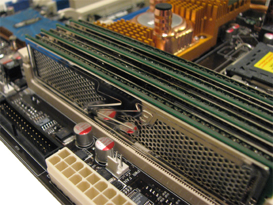
We found configuring our OCZ Platinum DDR3 PC3-14400 memory to run at their full-rated DDR3-1800 speed to be exceptionally simple. What's more, our ASUS Striker II Extreme had no trouble clocking even 8GB of top-end OCZ memory to DDR3-2000 speeds and above - something worth writing home about as far as we are concerned.
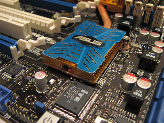
ASUS' MCP cooler is actually quite large - and for good reason, too. The NVIDIA 570i MCP can get very toasty doing a whole lot of nothing. Since it is attached to all the other major heat loads, it is entirely possible we were just seeing the effects of heat transfer from the hotter portions of the heatsink.
If you look closely, you can see the three LEDs located near the bottom-right corner of the cooler. The CPU, SPP, MCP, and memory each have a set of indicator lights - one green, one yellow, and one red - called "Voltminder LEDs". They give the user a quick way of determining roughly how hard each component is pushed. Green signifies that the component is seeing relatively low voltages, yellow warns of increasing stress while red is viewed as a stern warning that damage could occur without the proper precautions (i.e. increased cooling).
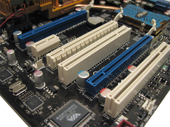
The Striker II Extreme has support for both 3-way SLI and Quad-SLI configurations, in addition to the more traditional 2-way SLI setup. The two blue PCIe x16 slots are PCI Express 2.0 compliant and should be used before a third graphics card is installed in the third white PCIe x16 slot (which is PCI Express 1.x compatible only). You can read more about performance tuning for graphic cards in our included 790i BIOS tuning guide.
The first PCIe x1 slot (black in color) can be used for either the included SupremeFX II 8-channel HD audio card or any other PCIe x1 device. A second PCIe x1 slot sits directly below the primary graphics slot. A pair of PCI 2.2 slots round out the board's expansion capabilities. Those that rely on wireless networks for connecting to the internet and/or other LAN resources will need to buy a separate wireless adapter as the Striker II Extreme only includes two hardwired RJ45 ports for Ethernet connectivity.


23 Comments
View All Comments
seamusmc - Friday, April 11, 2008 - link
For folks considering this board, I strongly recommend visiting xstremesystems.org's forums.Several people are experiencing data/OS corruption when performing any FSB overclocking. (Brings back memories of the early days of the 680i.)
nomagic - Friday, April 11, 2008 - link
LGA775 Core2 Duo/Extreme/Quad, Pentium EE, Pentium D, Pentium including next-generation 45nm CPU supportWhich would include Nehalem, I suppose? Should I also assume that a BIOS update would be required for Nahalem support? Is it possible that a custom board like this might have trouble supporting Nehalem when the times comes?
TemjinGold - Friday, April 11, 2008 - link
No. NOTHING out right now can support Nehalem as that's a completely different socket (different pin count too).